
Duct radiator operation
Always primarily follow the connection plan provided by the HVAC designer or heat pump manufacturer. Remember to also read the duct radiator’s instructions for use.
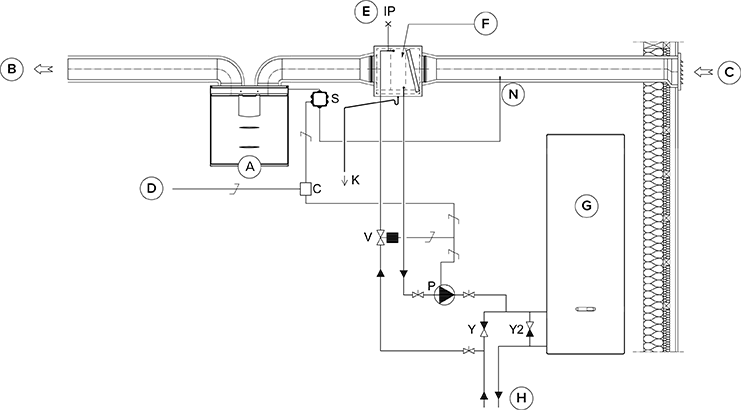
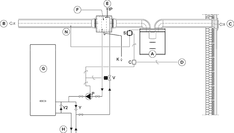
The accompanying figure shows an example of the arrangement for connecting the heating/cooling radiator unit to the heat collection circuit.
If the duct radiator is used in the supply air duct, it can only be used for cooling.
The output pipe of the radiator unit is connected to the return pipe of the heat collection circuit. The liquid returning from the radiator unit is circulated back to the heat collection circuit’s return pipe. If it is known that the pressure losses inside the heat collection circuit’s heat pump are too great, bypassing the heat pump is recommended. In that case the liquid is circulated when the heat pump is at rest, and the pressure loss of the bypass’ one-way valve Y2 must be smaller than the pressure loss of the heat pump.
Heating: The pump is switched on when the outdoor air temperature drops below the factory-set winter limit (-5°C).
Cooling: The target supply air temperature set for the unit’s mode (e.g. At Home mode) determines when the pump is switched on. The pump is switched on when the supply air setting is lower than the temperature of the air supplied.
The duct radiator can be installed in the supply air duct or the outdoor air duct. If the radiator is placed in the outdoor air duct, it can be used for pre-heating and cooling. If the radiator is placed in the supply air duct, it can only be used for heating or cooling.
To control the outdoor air duct radiator, an external NTC sensor is installed in the outdoor air duct before the radiator. To control the supply air duct radiator, an external NTC sensor is installed after the radiator.
The duct radiator can be set to work automatically or manually.
To prevent the risk of condensation in the supply air duct, you can set the adjustment of the supply air limit to automatic or manual.
If you are using an external sensor, go to the external sensor settings and select either outdoor air duct radiator or supply air duct radiator control. The external sensor’s temperature reading is displayed in the maintenance menu: .
When choosing the relay (C), take into account the maximum joint power supply of the motherboard of the MV electric box (max. 6 W), if the relay is supplied by the motherboard’s +24 V connector.
Due to the risk of humidity damage, in a duct that has not been insulated for condensation the supply air temperature must not fall below +16 … 20 °C.
| Name | Name | ||
|---|---|---|---|
| A | Ventilation unit | P | Circulation pump. Not included in delivery. Due to a risk of condensation, use a pump that is suitable for pumping liquid colder than the environment (e.g. Grundfos Magna 1 25-80). |
| B | Supply air | V | Solenoid valve. Not included in delivery. The valve should be suitable for heat collection circuit liquid (e.g. Danfoss 032U161431, HVAC code 4122110). |
| C | Outdoor air | K | Condensing water tube. Not included in delivery. |
| D | Feed from the distribution board | IP | De-aerator. Not included in delivery. |
| E | Air extraction | S | External electrical junction box for the MV |
| F | Duct radiator (reverse connection) | C | 24 VDC Relay/contactor for controlling the pump and solenoid valve. Not included in delivery. (e.g. ABB CR-P024DC2). |
| G | Heat pump | Y | One-way valve. Not included in delivery. |
| H | Heat collection circuit | Y2 | One-way valve. Not included in delivery. The pressure loss must be smaller than the pressure loss of the heat pump. |
| N | External NTC sensor |