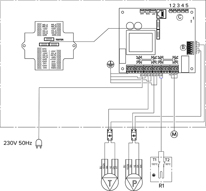
| A | Motherboard | D/l2 | Digital input 2 |
| B | - Extract air fan tacho (WT)
- GND (GN)
- Extract air fan PWM (YE)
- Supply air fan tacho (WT)
- GND (GN)
- Supply air fan PWM (YE)
| 11V1 | 11.1 V operating voltage |
| C | - Extract air
- Outdoor air
- Supply air
- Exhaust air
- Supply air from the HR cell
| AN/I | Analog input 0–10 VDC |
| D | LAN | RM/I | 24 V relay input |
| MB_A | External Modbus A signal | RM/O | 24 V relay output |
| MB_B | External Modbus B signal | T | Supply air fan |
| +24V | +24V voltage (DC) | P | Extract air fan |
| GND | Digital and analog ground potential | M | Damper motor |
| RS_A | Local hardware Modbus A signal | AHS | Post-heating control |
| RS_B | Local hardware Modbus B signal | CO2 | Internal carbon dioxide sensor |
| NTC | External temperature sensor connector | %RH | Internal humidity sensor |
| D/l1 | Digital input 1 | R1 | Post-heating resistor with 90°C and 130°C overheating protection |