Duct radiator operation charts
Always follow first and foremost the connection diagram provided by the HVAC designer or heat pump manufacturer. Also read the duct radiator manual.
Enclosed is an example of connecting the duct radiator to the heat collection circuit.
Connect the duct radiator output pipe to the heat collection circuit return pipe. The fluid returning from the duct radiator is directed back to the heat collection circuit return pipe. If the pressure loss inside the heat collection circuit of the heat pump is known to be high, it is recommended that the heat pump be bypassed. When this happens the pressure loss in the one-way bypass valve Y2 must be lower than the pressure loss in the heat pump.
When a duct radiator is used, it is recommended that the supply air duct of the ventilation unit be located in heated indoor premises (e.g. inside a false ceiling). If the duct radiator is used both for preheating and cooling, it must be installed in the outdoor air duct before the ventilation unit. In this case, the pump and the solenoid valve can be controlled using a Vallox MV ventilation unit, and no separate thermostats are needed.
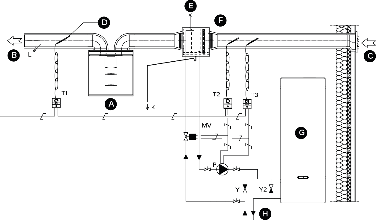
| Code | Description |
|---|---|
| A | Ventilation unit |
| B | Supply air |
| C | Outdoor air |
| D | Feed from the distribution board |
| E | Air extraction |
| F | Duct radiator (reverse connection) |
| G | Heat pump |
| H | Heat collection circuit |
| K | Condensing water tube. Not included in the delivery. |
| MV | Solenoid valve. Not included in the delivery. The valve that is chosen must be compatible with the heat collection circuit fluid (for example, Danfoss 032U157131). |
| P | Circulation pump. Not included in the delivery. The circulation pump must be compatible with the fluid used in the heat collection circuit, and its capacity must be correct. (For example, Grundfoss Magna 1 25-80) |
| L | Supply air thermometer. Not included in the delivery. |
| T1-T3 | Thermostats. Not included in the delivery. |
| Y | One-way valve. Not included in the delivery. |
| Y2 | One-way valve. Not included in the delivery. The pressure loss must be less than the pressure loss of the heat pump. |
Note
In heating, the pump starts when the outdoor air temperature drops below the factory-set winter limit value (-5 °C).
Note
In cooling, the value set for the supply air temperature of the active profile (e.g. At home) controls the startup of the pump. The pump starts when the supply air setting is below the temperature of the supply air that is blown into the apartment.
Note
When selecting the relay (C), take account of the maximum allowed combined power supply (6W) of the circuit board in the external MV connection box, if the relay power supply comes from the circuit board’s +24V connector.