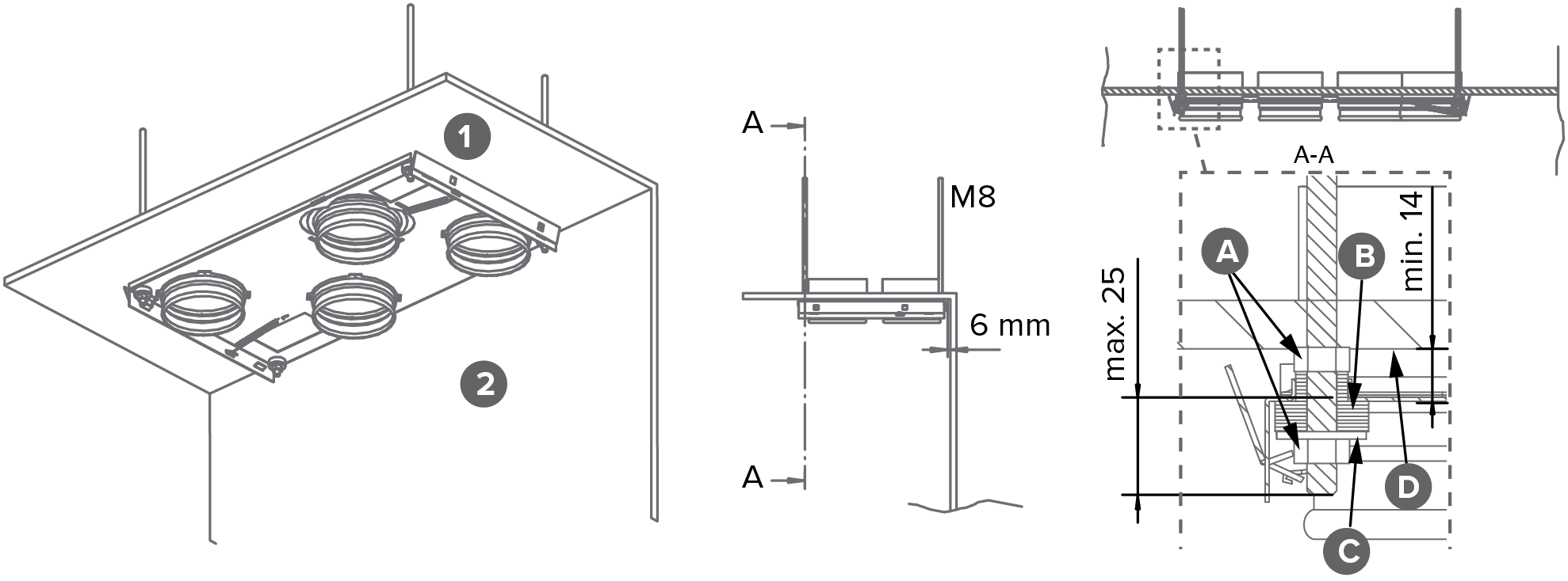
Mounting on the ceiling (Vallox 90 MV)

Vallox 90 MV can be equipped with an optional ceiling mounting plate. To attach the ceiling mounting plate:

  • On rafter frames or other frame structure with M8 thread bars so that they withstand the weight of the unit.
  • Horizontally, because the levelness of the ceiling mounting plate determines the levelness of the unit.
  • There is a 6 mm space between the rear edge of the ceiling mounting plate and the wall when the back of the ventilation unit touches the rear wall.
  • The minimum distance between the bottom surface of the ceiling mounting plate and the false ceiling is 14 mm. When this minimum distance is used, the distance between the top of the unit mounted on the ceiling mounting plate and the ceiling is around 2 mm.
Note: Mount the ventilation unit in a place where the temperature does not fall below +10°C.

Insulate the outdoor air and exhaust air ducts against condensation also between the unit and the ceiling mounting plate.

  1. Attach the ceiling mounting plate:
    1
    Ceiling
    2
    Wall
    1. Attach the M8 thread bars to the ceiling and turn the nuts to the bars.
    2. Shorten the lower ends of the thread bars so that they will be at no more than 25 mm from the lower surface of the ceiling mounting plate. Thread bars can only be shortened before the ceiling mounting plate is installed.
    3. Lift the ceiling mounting plate in place.
    4. Push a rubber damper (B) and a washer (C) onto each thread bar and, ensure that they touch the bottom of the cups of the plate.
    5. Turn the nuts (A) to make sure that the unit is horizontally level. Lastly, fasten the screws.
  2. Install the ventilation unit on the ceiling mounting plate:
    Warning:

    The ventilation unit is very heavy. Do not perform this procedure alone.

    1. Remove the front panel (1) of the unit (leave it hanging from the air flow measuring tubes).
    2. Place the connection box cables into the slot in the top part of the side panel (2) and pull the connection box to the side of the unit so that the cables remain in the slot.
    3. Ensure that the condensing water insulation is in place in the duct outlets of the extract air duct and of the duct that comes to the unit from outside.
    4. Lift the unit in its place on the ceiling mounting plate until both locking wings (3) lock on the outer edge of the side plate of the unit.
    5. Visually check the tightness of the duct outlets and the unobstructed passage of measuring tubes and electric cables.
    6. Put the front panel back in place.
    Tip:

    You can detach the unit from the ceiling mounting plate by pulling the spring-loaded moulding to the direction shown by the arrow (more detailed information is provided with the ceiling mounting plate).

Attic floor penetration plate

The attic floor penetration plate is optional. When an attic floor penetration plate is used, the airtightness of the vapour barrier must be ensured.

The minimum distance of the attic floor penetration plate from the rear wall is 5 mm. The minimum distance of the attic floor penetration plate from the side walls is 15 mm.