Mounting on the ceiling (Vallox 096 MV/Vallox 110 MV)

Vallox 096 MV and 110 MV can be equipped with an optional ceiling mounting plate. To attach the ceiling mounting plate:

  • On rafter frames or other frame structure with M8 thread bars so that they withstand the weight of the unit.
  • Horizontally, because the levelness of the ceiling mounting plate determines the levelness of the unit.
Note: Mount the ventilation unit in a place where the temperature does not fall below +10°C.

Insulate the outdoor air and exhaust air ducts against condensation also between the unit and the ceiling mounting plate.

  1. Attach the ceiling mounting plate:
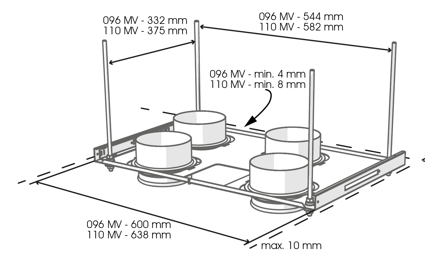
    1. Fasten the thread bars on the rafter frames or other frame structure, and turn the nuts onto the bars.
    2. Lift the ceiling mounting plate in place.
    3. Push a rubber damper and a washer onto each thread bar and, ensure that they touch the bottom of the cups of the plate .
    4. Turn the nuts to make sure that the unit is horizontally level.
    5. Shorten the lower ends of the thread bars so that they will be at no more than 10 mm from the lower surface of the ceiling mounting plate.
  2. Install the ventilation unit on the ceiling mounting plate:
    Warning:

    The ventilation unit is very heavy. Do not perform this procedure alone.

    1. Install the ceiling mounting plate with M8 thread bars so that it is horizontally level.
      Note: The end of the thread bars must be 5 mm or less below the fastening nut. Do not fasten the ceiling mounting plate too tight to the ceiling. Ensure that the sliding bars move and restore to their original position by pulling from the operating levers (A). The top edge of the white covering strip of the ceiling mounting plate can be installed against the ceiling. Alternatively, a concealed mounting method can be used, in which case the ceiling can be 20 mm below the top of the white covering strip.
    2. Install or check insulation washers:
      • 096 MV: Install the insulation washers into the outlet collars of the ventilation unit.
      • 110 MV: Ensure that the insulation washers are in the outlet collars below the ceiling mounting plate.
    3. Remove the door before installing the ventilation unit to the ceiling mounting plate.
    4. Lift the ventilation unit close to the ceiling mounting plate and feed the cables and the connection box through the hole in the ceiling mounting plate on top of the ceiling.
      Note: Remember to make a service door in the ceiling so that the cables and the connection box can be accessed. The distance between the service door and the ceiling mounting plate must be around 500 mm.

      Alternatively, the cables can be fed to the rear wall between the ceiling mounting plate and the ventilation unit. When the ventilation unit is lifted against the ceiling mounting plate, the unit locks in place. Where needed, guide the mounting hooks on the ceiling mounting plate (B) to the grooves on the side panels of the ventilation unit. There are operating levers (A) on the front bottom corners of the ceiling mounting plate. When the levers have been restored to the same level with the white covering strip of the ceiling mounting plate, the unit has been locked in place.

    5. Where required, the unit can be detached from the ceiling mounting plate. Remove the door of the unit. Lift the unit slightly upwards and pull simultaneously from both operating levers (A) of the ceiling mounting plate to detach the unit from the ceiling mounting plate.

Attic floor penetration plate:

The attic floor penetration plate (F) is optional. When an attic floor penetration plate is used, the airtightness of the vapour barrier must be ensured.

The minimum distance of the attic floor penetration plate from the rear wall is 5 mm. The minimum distance of the attic floor penetration plate from the side walls is 15 mm.